Step 1
Start from the middle of the wire and wind it tightly around the glue stick 30 times. Make the winds neat and close together.
Step 2
Gently remove the coil from the glue stick.
Step 3
Wind the free ends of the wire around the coil to prevent it from unwinding.
Step 4
Straighten the free ends of the coil. The total length of the coil and free ends should be approximately 4 cm longer than the length of the battery. Trim off any excess.
Step 5
Place one of the ends of the coil on a work surface and use the blade of the craft knife to scrape off the insulation on one side of the wire. Repeat for the other end, making sure that the same side of the wire is scraped.
Step 6
Thread one of the free ends of the coil through the spring of one of the safety pins. Repeat with the other free end and the second safety pin.
Step 7
Tape the magnet to the centre of the battery.
Step 8
Tape the clasp of one of the safety pins to one terminal of the battery. Repeat with the clasp of the other pin, at the opposite end of the battery.
Step 9
Gently adjust the coil so that it is directly above the magnet. Straighten the free ends of the wire.
Step 10
Fasten the battery to the insulating surface using tape.
Step 11
Spin the coil first in the clockwise and then in the anticlockwise directions and observe what happens in each case.
- An AA battery could be used instead of a D battery.
- While stripping the wire, place the wire on a flat table and hold in place with one hand. With the other hand use the knife to scrape the insulator. Move the knife away from you, i.e. towards the end of the wire. Keep hands well clear of the blade.
- When the craft knife is not in use, replace the safety guard.
- Refrain from touching your face or eyes throughout the experiment, since magnets tend to attract fine metal dust.
- Wash hands thoroughly with soap and warm water following the experiment.
- Magnets pose a serious health threat if ingested.
Imagine you’re going for a run. Before setting off, you need to eat in order to store up enough energy in your body to get through the run. This energy doesn’t remain in your stomach but is distributed throughout your body. As you run, this stored energy gets converted into movement in your arms and legs. The more energy you have stored, the further and faster you can run. Eventually, you use up all the stored energy and must slow down and stop running. Motors work in much the same way. The battery in the circuit stores the energy needed by the motor to move – so it’s like the food intake into your stomach. The distribution of energy all round your body is like the current flowing in the motor coil. Finally, the movements during the run represent the rotation of the motor. The greater the stored energy in the battery, the longer the motor can run. The motor can run faster if the current is greater. Eventually, the battery is exhausted, just like you after a run, and the motor stops moving.
Why does current flow from one end of the battery to the other?
There is a complete chain of conductors.
Why was the insulator removed from the wire?
To complete the circuit.
What does the magnet produce around it?
Magnetic field.
Why does the coil not move when turned in the opposite direction?
The fields attract.
When will the motor stop?
When the battery is exhausted.
The battery, paper clips and winding create a complete circuit. Direct (DC) current flows out from the positive end of the battery, through the circuit and into the negative end. As current flows through the winding, it creates a magnetic field. The right grip hand rule can be used to determine the direction of the field. The thumb points in the direction of current flow and the fingers ‘grip’ the wire in the direction of magnetic field. The magnet also creates a magnetic field.
In magnetics, two similar poles (North-North or South-South) repel, while like poles (North-South), attract. When the current in the wire does not flow perpendicular to the field produced by the magnet, the field produced the current is repelled by that of the magnet. This results in a force which makes the coil move. If all the insulation around the ends of the coil were removed, when the coil reaches the vertical position, the current is perpendicular to the magnet’s field and the fields would attract each other, ceasing motion. Leaving the insulation present stops current flow in the coil, allowing it to be carried by its own momentum past the vertical position.
Spinning in the opposite direction had no effect since the fields were attracted and not repelled. The motor continues to run until the battery power is exhausted.
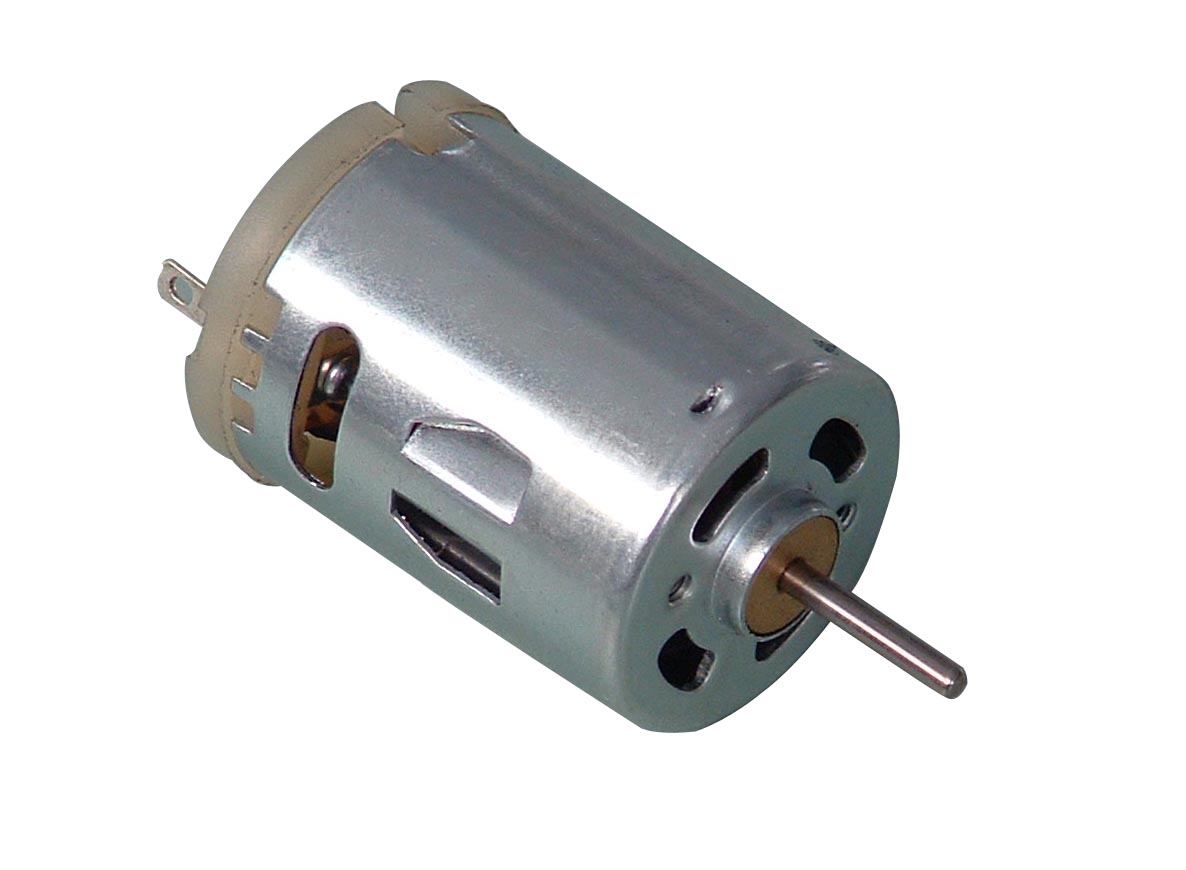
The setup is analogous to a DC motor. The coil represents an air-wound armature winding in the rotor. The fixed magnet corresponds to the stator. Finally, the insulator on the free ends of the coil represents the action of commutators.
The motor converts input electrical power, expressed in terms of current and voltage, to mechanical power, which manifests as torque and angular velocity. Linear relationships exist between the electrical and mechanical component of the motor, through a constant parameter, k:
[latex]T = kI[/latex] [1]
and
[latex]V_{s} = k\omega[/latex] [2]
Where: I is the supply current, Vs is the supply voltage, T is the torque acting on the armature and ω is the angular velocity of the armature.
The potential difference across the battery causes a current to flow through the coil. The opposition of the field produced by the current and that of the fixed magnet produces a torque which gives the armature an angular velocity. The magnetic field of the fixed magnet induces a back electromotive force (EMF), E, across the coil. E opposes the supply voltage.
For a DC motor with brushes, back EMF generated is related to the motor parameters as follows:
[latex]E= P\phi ZN/60A[/latex] [3]
Where: P is the number of poles in the stator, φ is the flux per pole, A is the number of parallel paths, N is the speed of the motor.
Thus, the voltage across the armature, Va, is equivalent to:
[latex]Va =Vs – E[/latex] [4]
where Vs is the supply voltage. The current through the armature is therefore equal to:
[latex]Ia = Va/Ra[/latex] [5]
where Ra is the resistance of the armature.
Applications
Different types of DC motors are used in different applications. They are used in construction (cranes and air compressors), domestic appliances (sewing machines and food processors), industry (conveyors, presses, elevators).
DC motors are popular because they enable variable control of speed. They also sustain full torque at all speeds, making them useful in industrial applications, which require predictable and constant performance. Other types of motors are much less flexible. DC motors will also play a big role in the future of surgical robotics. This is mainly due to the fact that special DC servomotors can be precisely positioned and operate at high speeds.
Research
DC motor research is being used to develop systems which can accurately control the movement such motors. One area of focus is preventing noise – random instabilities in circuitry – from affecting the control of high power motors. Another area focuses using new digital methods for better control of the torque and speed of motors.
- Use different batteries with larger and smaller voltages.
- Vary the number of turns in the coil.
- Vary the diameter of the coil.


