Step 1
Create a hole into the top of the cup using the drill and screw.
Step 2
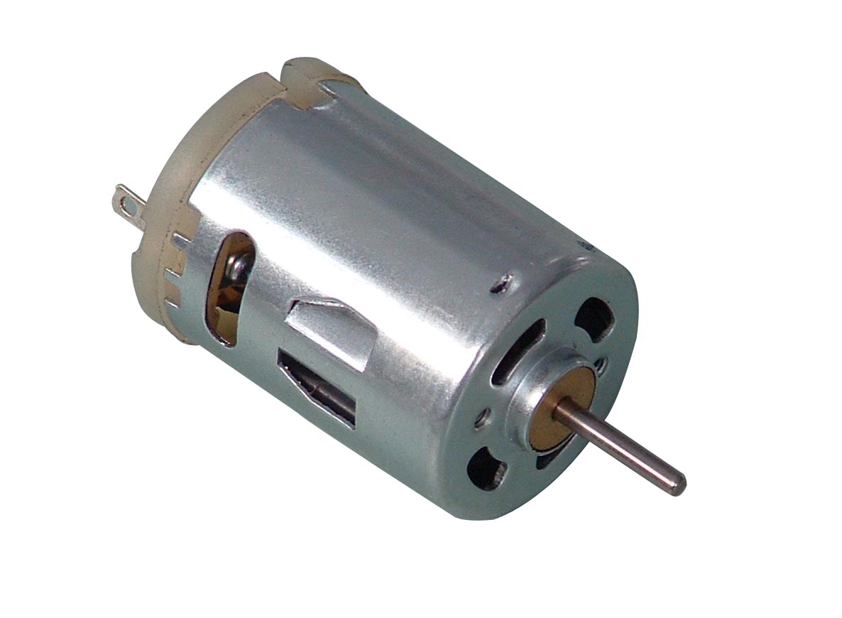
Insert the shaft of the motor into the hole. Fix the body of the motor to the top of the cup using glue.
Step 3
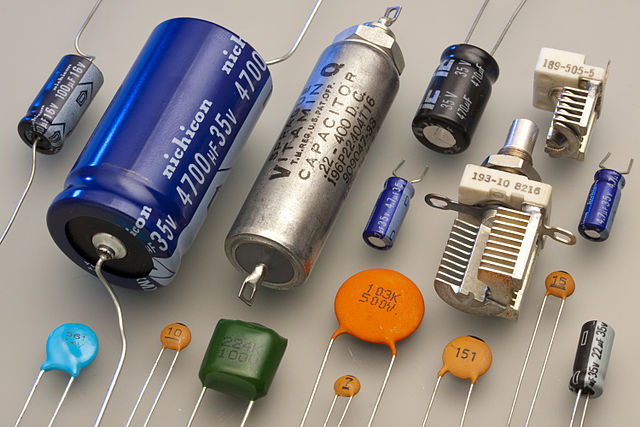
Glue the battery to the top of the cup, beside the motor.
Step 4
Attach piece of breadboard wire to each of the terminals of the motor. Knot the wire to the connector or secure with a dot of glue.
Step 5
Attach one of the wires connected to the motor to the positive supply terminal of the battery using a dot of glue.
Step 6
Glue the crocodile clip to the end of the wire connected to the other terminal of the motor.
Step 7
Glue the felt pens around the cup. Make sure they are equally spaced out.
Step 8
Place a plain paper down on the worktable.
Step 9
Remove the lids of the markers and place the machine on the paper.
Step 10
Connect the crocodile clip to the negative terminal of the battery and observe what happens.
Step 11
To stop the machine, disconnect the crocodile clip from the battery.
- The motor does not have to be purchased but could be salvaged from an old toy, as long as the specifications of the motor are similar to those suggested in the ‘Materials Required’ section.
- An adult should operate the drill.
- Help keep our environment clean by reducing waste, reusing materials, and recycling whenever possible!
- When drilling into the cup, excessive pressure may cause the cup to crack. Apply gentle pressure.
- The hot glue gun should be used with the help of an adult and under strict supervision since the hot glue is a burn risk. Younger children should not be allowed to operate the device.
- Use adequate protection to prevent the work surface from being damaged by the hot glue or the colours.
- Make sure the markers are aligned so that the machine can operate properly.
Imagine you’re sitting all comfy on a sofa. But then your friend comes along, and asks if you want to go for a hike. It’s a lovely day, but you just don’t want to move – your chill time is just too appealing. Your friend, however, is very insistent, manages to convince you, and off you go.
It’s a hot day and your hike is full of hills. It takes a lot of effort for you to put one foot in front the other, but you’ve got a good pace going and now that you’re moving, you don’t really want to stop.
You can imagine that, right? Well, then you already understand a bit about how robots work. You sitting comfy at home is like a robot at stand-still, what scientists call at rest. Your reluctance to move represents the inertia of rest of the robot. Your friend represents the force causing the robot to start moving, by overcoming the frictional forces keeping the robot at rest.
While you’re on your hike, the obstacles trying to stop you represent the frictional forces which try to stop the robot from continuing to move. Your desire to keep up your pace is like the robot’s inertia of motion, which makes it reluctant to stop moving once it starts.
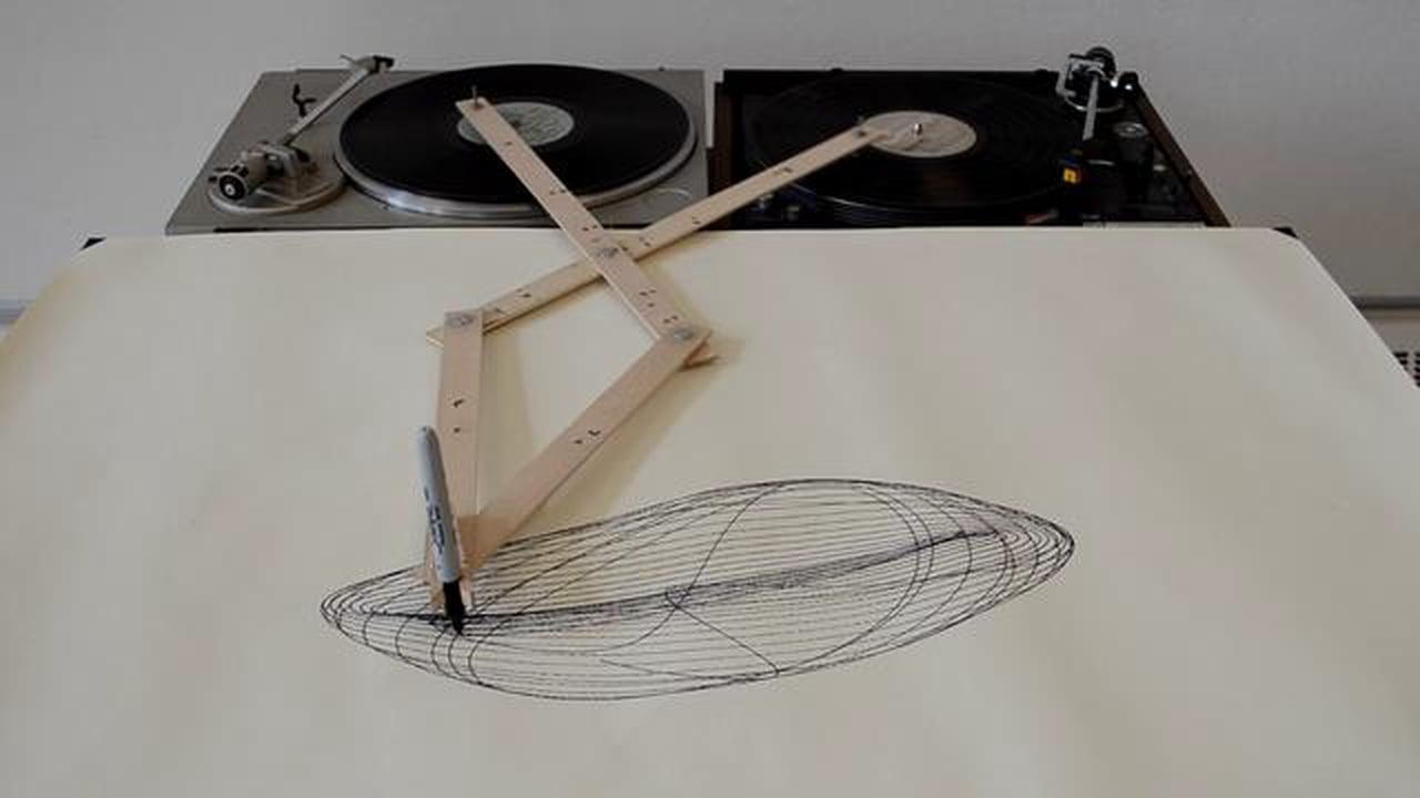
Why does the cup rotate?
The motor shaft rotates, causing the cup to rotate.
Why does the cup move with a jerky motion?
The markers are not perfectly aligned. Also, the motor has to overcome friction and the weight of the machine.
Why does the cup stop moving?
The motor was disconnected from the battery.
Why can the motor make the cup move?
The motor produces enough (kinetic) energy to move the cup.
What forces act on the cup?
Torque from the motor and friction.
The motor transforms chemical energy within the battery to kinetic energy in the axle. The axle uses this energy to rotate. The power provided by the motor is sufficient to cause the cup to rotate with the axle. The motor must overcome the machine’s inertia and frictional forces in order to move the cup.
Any object at rest (not moving) has some reluctance to begin moving and an object which is already moving is reluctant to stop moving. This reluctance is known as the object’s inertia.
The motor must also overcome the friction between the pen nibs and the paper, which opposes motion. Before the object begins moving, this force is known as static friction. Static friction occurs due to the ‘roughness’ of the surfaces. Once the machine begins moving, the forces change to dynamic frictional forces. These frictional forces are due to irregularities in both the touching surfaces. When they are pressed together, these irregularities push against each other and work to resist motion of either object.
While the axle only rotates, the cup moves translationally and it also rotates. This indicates manifestation of both kinetic energy of translation and kinetic energy of rotation in the system.
Kinetic energy of rotation:
k.e.rot = ½ Iω2 [1]
Where I is the moment of inertia of the object, ω is the angular velocity.
Kinetic energy of translation:
k.e.translation = ½ mv2 [2]
Where m is the mass of the object, v is the translational velocity.
Heavier objects have greater inertias of rest and motion. An object’s moment of inertia represents its reluctance to rotational motion, measured in kg m2. This depends heavily on the distribution of the object’s mass about its axis and is calculated based on the shape of the object.
The frictional force between two stationary, touching, surfaces is called static friction. This friction prevents motion up until the forces promoting motion surpass a threshold determined by the coefficient of static friction.
The dynamic friction produces a force which opposes the relative motion of two objects against each other. The magnitude of the frictional force depends on the coefficient of kinetic friction associated with the two surfaces.
Applications
Motors similar to the one used in this experiment are widely used in motorized toys bought from shops, as well as made by people as a hobby. These include toy cars, planes, robots and miniature generators. They can be powered via a battery, a solar panel or a wind turbine.
Larger scale DC motors are used in some electric cars.
Research
There has been a surge in research into DC motors used in electric and hybrid cars. One area of interest has been modular motors. These motors can be scaled by adding modules in order to vary the power of the motor according to the vehicle it is used in, be it a small car or a truck. This involves designing new converters and power management schemes.
- Change the battery to a 1.5V battery. The machine will be observed to move very slowly or not at all. This is because the battery voltage and current capability of the battery are not adequate to power the motor.
- Add extra markers to the cup. Observe how each additional marker affects operation.
- Swap the battery connections and observe how the direction of axle rotation is affected.